The Network Capture Playbook Part 4 – SPAN Port In-Depth
We have briefly covered SPAN ports in previous posts of this series, but there are so many things to consider that we have to look at the advantages and problems more closely. Even more so since it looks like there is a constant “battle” going on between SPAN and TAP supporters – some analysts will tell you “you need to use a TAP!” while others will say the opposite.
SPAN Ports
I said it before and I’ll probably say it again a few more times in this blog post series: in capture situations, it always comes down to the question “how precise do you need your capture to be?”
The goal of this blog post is to give you as much information about practical SPAN port usage in real life network analysis situations with all the advantages and disadvantages so that you can decide yourself if a SPAN port is good enough (read: “precise enough”) for what you need to do.
Refreshing the basics
This part will refresh some of the things I’ve have already covered in the first post of the series, mostly because some readers may jump into this part without bothering reading the other parts first. As you may already know SPAN ports are a switch feature which is required if you want a copy of packets you won’t usually get. Keep in mind that this feature requires the switch to be configurable, so a “dumb” 5 to 16 port switch may not be able to do this at all unless it’s a special switch hardwired to mirror packets.
“SPAN” stands for “Switch Port ANanlyzer”, and if I remember correctly it was a feature originally invented with the idea of being able to debug switch functionality and not for troubleshooting of endpoint conversations. Today, SPAN is almost always used for packet analysis, listening in on packets between devices that you’d normally not see. For that, an administrator configures source ports, which are the ports you want to get the packets copied from (also called “mirror” ports) and a destination port (“monitor” port). It may be worth noticing that a monitor port is just any regular port on the switch, which gets the role of becoming a monitor port through the configuration of the SPAN session.
For most switches, monitor port behavior is different from that of the normal ports, because a monitor port stops accepting packets from a connected device. This means that most monitor ports will only send packets from the switch to the capture device attached to it, but drop anything coming in from the capture device. This is important for multiple reasons: a capture device is prevented from messing with the production network, which is a good idea. But it also means that as soon you configure a port as monitor port, you cannot use it anymore to talk to anyone (including the switch). So be careful not to lock yourself out by configuring the monitor port on the one single port that has an IP address for switch management (otherwise you’re going to have to go serial console mode I’m afraid, and if the switch doesn’t have one, a factory reset is probably your only option to recover the device) 😉
There are some switches for which a monitor port continues to work like the normal switch ports do (meaning, receive and transmit work as usual), which is something you need to be aware of. Especially cheap switches and those with hardwired monitor ports may do this, so if you’re not sure, test first.
The good SPAN
SPAN ports can be really useful:
- They allow convenient access to packets you’d normally not see at all without having to buy additional hardware
- Using a SPAN port comes with no network link interruption
- SPAN sessions can be turned on and off with more or less simple CLI commands or a Web interface
- SPAN can provide aggregated access to multiple source ports or even VLANs
1. Access to packets
As another reminder, without SPAN ports, your capture device would not see the packets you want to capture, because the switch will only forward them between the two devices talking to each other:

Figure 1: Switching without SPAN
So with a SPAN / Mirror feature, the switch will send copies of all the packets on the “mirror” port to a “monitor” port where the capture device is connected:
Figure 2 – Copies sent to the capture device
2. No network link interruption
Enabling SPAN is usually a simple thing to do: you don’t have to unplug any production link (unless all ports are in use and you do not have a free port for the network capture device), and just configure the switch to send copies of a port to the “monitor” port. The only thing left to do is to find a free port you can use as monitor port, and connect the capture device to it (usually a Laptop or other PC)
3. Configuration via CLI or Web GUI
This can be done either via CLI, or… okay. All of you now yelling “CLI! Nobody with any kind of sysadmin skill will ever use a web GUI” – I hear you. You’re right. But still there is… a web GUI. Web GUIs may be the only option for cheap switches like I listed at the bottom of the first post of this series. It may be worth noticing that some switches make it hard to find the right configuration option, but with a little help from Google or other search engines it’s usually easy to find the correct command or location in the GUI. Here are some examples I used before:
Cisco CLI example:
Switch(config)#monitor session 1 source interface gigabitEthernet 1/7 both
Switch(config)#monitor session 1 destination interface gigabitEthernet 1/24
HP Web GUI example:
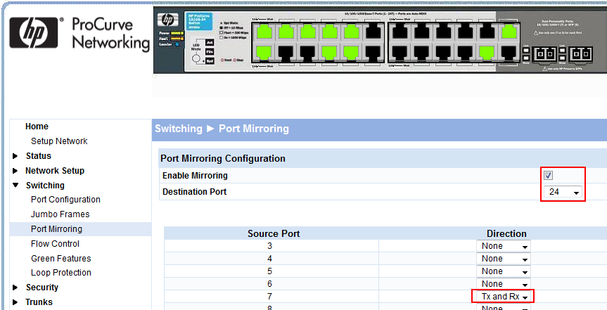
Figure 3: HP SOHO Switch Web GUI
You can specify if you want to packet to be mirrored when it enters a port, or if it leaves a port, or both (see “TX and RX” in Figure 3, or the “both” parameter in the Cisco example above). If you’re only SPANning a single source port, you usually want “both”, because otherwise one side of the conversation will be missing. The main reason for specifying only one direction is that it gives greater flexibility in situations where mirroring both directions leads to duplicates in the trace (we’ll talk more about those later in this post).
By the way, there are still some very old switches out there that are manageable but don’t have a SPAN feature (last thing I saw this was at a German hospital a few years ago, still running old 3COM Superstack switches). If you find a switch like that, make a mental note to replace it yesterday (no smiley here. It’s that important).
4. SPAN can provide aggregated access to multiple sources
Most switches allow adding more than one source port to the SPAN configuration, meaning that you can capture multiple devices or links at the same time on a single monitor port. Professional switches (I try to draw the line at “has a command prompt with an “enable” and “config” command, and with an active maintenance contract) also allow specifying one or more source VLANs, which slowly becomes available for more and more cheap manageable switches as well.
Spanning a VLAN means that you get access to all packets entering and/or leaving the switch which are part to the VLAN or VLANs you specify. While this may sound very convenient you need to be extra careful if you do this, and we’ll see why later in this post. Also, keep in mind that specifying a source VLAN may not give you all packets in the VLAN: you’ll only get those that have to pass through the switch the SPAN session is running on! It’s not a magic “give me all the packets!” weapon, sorry.
If you want, you can configure a switch to mirror all switch ports or VLANs to the monitor port – many inexperienced home users or even professional network administrators think of this as a “great way to monitor everything on the network”. Nope. Its really not a good idea, and we’ll see why soon (the keyword is “bandwidth bottleneck”).
The bad SPAN
Unfortunately, SPAN ports are not always good enough in a capture situation. There are some problem scenarios that make it hard or impossible to use a SPAN port, no matter how convenient it may be, because it does not provide the precision required or may hurt the network. The list of SPAN problems includes:
- Bandwidth bottleneck at the monitor port
- Stressing the switch CPU
- Insufficient precision
Bandwidth bottleneck at the monitor port
Bandwidth bottlenecks are a major problem of SPAN sessions, even when you’re only mirroring a single port to a monitor port of the same bandwidth, e.g. creating a SPAN session that forwards all packets on a 1Gbps port to a 1Gbps monitor port. The reason for that is something I already talked a lot about in the network card post of this series: a 1Gbps full duplex port has a combined maximum bandwidth of 2Gbps (1Gbps receive and 1Gbps transmit). The monitor port can only use transmit towards the capture device, which means that in a worst case scenario 2Gbps need to be pushed on a 1Gbps link. Now guess what happens if there’s a lot of traffic? Probably something like this:
Figure 4 – SPAN session dropping packets
The answer is: the switch will drop packets. This means that your capture device will only see an incomplete set of incoming packets, and doesn’t even know that there were drops, because they happened before the network card could ever see that there was an incoming packet. The switch has no way of signaling the capture device that it had to drop packets. So creating a SPAN port for a port where you know that the bandwidth is really high in both directions (e.g. a backbone link) is not a good idea. Or doing something like using SPAN to mirror a 10Gbps link to a 1Gbps link. You’ll end up with a capture file that has many warnings like this:
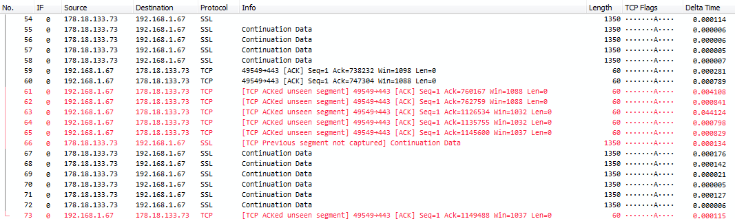
Figure 5: Example of packet drops occuring
Most likely you’ll see many small packets with the “ACKed unseen segment” warning created by Wireshark, because the big data packets couldn’t make it through, while the TCP acknowledge packets will be small enough to slip through the bottleneck.
The situation quickly escalates if you add more source ports or whole VLANs to the SPAN session. Let’s assume you need to capture what a virtualization host sends and receives, and it is connected to a Gigabit switch with 4 links. Since the virtual machines may use any of the 4 links based on some kind of load balancing policy you may need to capture all links at the same time. Configuring a SPAN port of 4 potentially highly saturated links will mean that you’ll face up to 8Gbps of total bandwidth, and if you use a 1Gbps monitor port, you’ll lose about 7 out of 8 packets if you’re unlucky. That’s not even close to good capture precision.
Stressing the switch CPU
Another important aspect of using a SPAN port is that it may put additional load on the switch CPU. This is something that depends on the make and model of the switch of course. While switches usually forward production link packets on a very fast hardware layer without having to involve the CPU in most situations, the story is often different with SPAN sessions. The CPU has to manage the mirroring process, so adding more and more source ports to a SPAN session can get the switch into trouble:
- Some switches react to this by skipping packets during the mirroring, meaning while the real packet still gets forwarded, the monitor port will not get a copy, or a delayed/out of order copy
- Other switches get into general trouble, losing or delaying packets on the production links as well as giving you incomplete monitor port copies
- Worst case I’ve seen is that the switch starts flooding all packets to all ports, which I refer to as the switch stating: “Okay, I give up, let’s go to emergency mode and pretend I’m a hub” 😉
Insufficient precision
The biggest problem of SPAN port captures is that the precision isn’t good enough in some capture situations. Those situations include
- High bandwidth environments: always keep in mind that SPAN ports have to aggregate receive and transmit bandwidth of the port(s) copied to the monitor port. So if you SPAN a 1Gbps full duplex link to a 1Gbps monitor port you have to consider if the total bandwidth might exceed 1Gbps (up to 2Gbps in total), in which case you’ll have to deal with packet drops.
Of course you could SPAN a 1Gbps full duplex port to a faster port, e.g. a 10Gbps monitor port to get around that problem. But that would require the switch having a spare 10Gbps port, and you having a capture device that can capture at that line speed – which means, Laptops are not an option for this, at the time of this writing in 2016, because they don’t come with 10Gbps ports. Most 10G ports are also fiber, and that’s another story entirely, because you’ll need a matching capture card for that. - When the task is to determine the location of packet loss: this one is an automatic “no go” for using a SPAN port.
The problem is this: if you determine in your capture file that a packet was lost at the point of capture, you have only proven that you didn’t capture it. My question to you would be this: “can you give a 99.99% guarantee that this wasn’t just because the SPAN session had to drop it caused by a mirror port bottleneck? Can you say for sure that this packet really never existed on the switch?”. No. You can’t.
I had a case where I had to prove that a firewall blocked some packets it should have let passing through, while others passed just fine. This problem is one of those that you cannot solve with a SPAN port – you need TAPs on incoming and outgoing links to prove this kind of thing (and because believe me, the firewall vendor will fight your capture analysis results tooth and nail if you didn’t use high precision capture TAPs. Been there, done that, many times). - Proving packet existence and delivery: can you guarantee that a packet left a switch on the production link just because you’ve seen it on the monitor port? I’ve had a situation where the packet was sent by the switch down to the server’s NIC which was faulty and ignored it – it’s not possible to be sure that the packet was on the wire with a SPAN session – it can only be assumed, and that may not be good enough in some situations (again, the server guy will often fight your results anyway he can). If you need to prove that the network is doing its job you can’t use SPAN based captures as proof that the packet was in fact delivered to the server NIC. You need to use a TAP instead.
- Determining packet delay between two points in the network (which is a complex task in itself in most cases): if you have to measure packet delay between two locations in the network you’re usually hunting for single digit milliseconds, down to nanoseconds in some cases.
I had a case where a software was migrated from a mainframe to Linux servers, and the TCP round trips to the database across the network was completely killing performance (see this blog post for background info on this kind of problem). So the customer wanted to know if the network was delaying the packets between the two servers, or if it was an application design issue (which is much more expensive to fix, so they hoped it would be a network problem). I knew that there were only three switches between the two servers, and as a rule of thumb switches do not add any kind of significant delay unless something is really broken or designed badly. Switching delay is also in the micro- to nanosecond range, and this ruled out using SPAN – because SPAN timings are distorted by the mirror process. You can’t trust mirrored packet timestamps on a micro- to nanosecond range, ever. So I had to use full duplex TAPs instead to prove the network was fine.
The ugly SPAN
When there’s good and bad, there’s usually also ugly, in this case meaning that something works but can be problematic:
- Packet queuing delay on the production links: some switches delay the packets on the production links during the SPAN mirror process for some reason. While those delays may not be that significant on a single packet base it can add up to annoying levels, so watch out for problems coming up with the production systems during a SPAN capture. They’re pretty rare, but it happens.
- Running into switches still on factory settings: I’ve been to a customer site where all switches had never been configured, running in default mode. It was kinda funny connecting to the default IP of a 24 port switch and getting a web interface of a 48 port switch (my first thought was that someone had messed up the web interface design, but no, it was a 48 port switch, a DLink if I remember correctly). The reason was that all switches had the same default IP address, and while the 24 port switch was the “core” the 48 port switches were the distribution layer. So why did I get one of the 48 port switches when I was physically connected to the 24 port switch?
Because: “last ARP answer often wins”. Think about this: my laptop ARPed for the default IP of the switch. Of course the 24 port switch answered first, but before my web browser connected to the IP, the other switches had answered just a little later as well, overwriting the ARP table entry for the IP. So I didn’t get the fastest device but one of the others. I had to reconfigure three switches to different IP addresses until I could finally access the switch I really wanted to access 😉 - Unstable switch OS: I hope this is a thing of the past, but I’ve seen huge professional core switches (there was a “sys” in the vendor name 😉 ) do a full device restart when a SPAN session was disabled again (that happened around 2006). Believe me, you don’t want a core switch to reboot outside of a maintenance window in a financial institution with high frequency trading, ever. So expect trouble when configuring SPAN sessions, either adding or removing them, unless you gathered some experience and know for sure that the switch can handle it. Or, to say it with Jack Reacher: “Hope for the best but expect the worst”.
- Duplicates: SPAN ports can give you duplicates that will wreak havoc on your analysis results if you aren’t aware of them. The main reason for duplicates is that the mirroring process creates copies more than once:
Figure 6: SPAN session resulting in duplicates
Duplicates usually only occur when you’re SPANning more than one port, as seen in the figure 6. It also happens if you SPAN a VLAN (or more than one) because it will give you the packet entering and leaving the VLAN on the switch, and it’s basically similar to a multi-port source SPAN. One way around this for VLAN SPAN is to specify that you only want packets entering the VLAN or leaving the VLAN, but not both. In most cases this will work fine, because now you get the same packet only once. You can’t avoid capturing duplicates when SPANning multiple ports.
Some (cheap?) switches may also give you duplicates when you’re only SPANning one port, because they’ll forward multicast and broadcast packets down the monitor port, plus copies of the same packets from the mirrored port.
See this blog post for more details on how do deal with duplicates and why it confuses the Wireshark TCP expert (and most other TCP expert systems I’ve seen).
- RSPAN: RSPAN is a technology to allow “Remote” SPAN ports, e.g. when a laptop is connected to a switch but the packet mirror is configured on another switch:
Figure 7: Remote SPAN via VLAN
Sometimes, RSPAN seems like a good idea, even though it has more to do with convenience from my point of view. I’ve seen network administrators use RSPAN because they didn’t want to sit in a cold and noisy data center when they could do the capture in the warm and comfortable office by having a VLAN transporting the packets to where they sat. I myself have two main problems with RSPAN though.
The first problem is that it puts additional load on the production network, because the copied packets need to be transported to the capture laptop via VLAN. This may not seem much, but if the network is already very busy it can lead to chaos. It can also lead to packet drops in the capture when the forwarded packets cannot pass a bandwidth bottleneck (SPAN packets are usually considered “first to drop” when there’s bandwidth problems)
The second problem is that the packet timings are heavily distorted, because they get time stamped on the capture laptop, which is more or less far away from the point where they passed by. In the end, any network analysis that has to do with timings or packet loss cannot be performed reliably with RSPAN – results can always be challenged, because the additional transport potentially messes things up.
- ERSPAN: ERSPAN is similar to RSPAN (including the problems), but instead of transporting the packets over a VLAN they are tunneled over a Layer 3 network, which allows packet captures across router boundaries (which often makes things worse, because routers are often additional bottlenecks):
Figure 8: Remote SPAN via Layer 3 tunneling
This is how a packet looks like when it’s transported in a tunnel (a capture file containing packets that carry packets for a capture file):
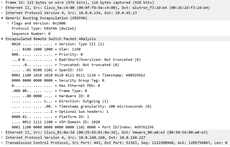
Figure 9: Example decode of an ERSPAN packet
You can see how the TCP packet is transported using a GRE header with the ERSPAN protocol type. The laptop capturing at the end of the ERSPAN path will only see the packet contents starting with the second Ethernet II header. And all the problems I have with RSPAN are also valid for ERSPAN, with the additional point that routers are often worse bottlenecks than switches.
- VLAN tags: in many cases, SPAN ports will not give you access to the VLAN tag information of VLAN tagged packets and only send copies of the untagged packet to the monitor port (or even keep them from you completely). This can be pretty annoying when you need the packets to be captured with VLAN tags intact. This is especially true if you’re capturing on a monitor port with the source being multiple VLANs, because if the VLAN tags are stripped you have no way of telling which VLANs the packets belonged to afterwards. Some switches can be forced to not strip the VLAN tag, e.g. by specifying the encapsulation type on some Cisco switches:
Switch(config)# monitor session 1 source interface fastEthernet0/5 both
Switch(config)# monitor session 1 destination interface fastEthernet0/24 encapsulation dot1q
I once had a problem with a Cisco switch (I think it was a Catalyst 6509) that didn’t have the “encapsulation” parameter for the monitor session. If I remember correctly we solved that problem by defining the monitor port as trunk port, resulting in the switch sending VLAN tagged packets to the capture device.
- LACP: A similar problems appears if you try to capture LACP communication which is used to negotiate link aggregation: the SPAN port will often simply not copy these to the monitor port (I’ve seen that behavior from Cisco and HP switches myself, but it may have changed in the meantime) – so if you expect to see LACP frames but do not, using a SPAN port may be the problem and you have to use a TAP instead.
- Trustworthiness: SPAN is a functionality programmed into the switch operating system – so if someone manages to infiltrate the network and manipulate the switch OS, mirrored packets may be modified or omitted. This means that when you use SPAN you need to keep in mind that it may hide the bad stuff from you. Which means that you need to use TAPs instead if you worry about that level of sophistication on the attacker side.
Final Words:
SPAN ports are useful, and they are by far the most common way of accessing packets, while they come with a couple of things to consider. But even though they’re not as precise as a good TAP, they are very often the preferred way to capture packets. To sum up their greatest features: they’re easy to set up, easy to remove, and they don’t hurt network connectivity. You could also say “they’re convenient”.
SPAN Best practices
- Don’t be afraid to use SPAN ports when the required capture precision allows it (see bullet list below for situations when it isn’t). Being able to avoid link down interruptions like you’ll have when inserting a TAP is a huge advantage for SPAN ports.
- Do you know the saying “Measure twice, cut once?” – it can be adapted for SPAN port configuration like this: “Determine source and destination ports for the SPAN session twice. Write them down. then configure once. Bonus: double check your configuration statement matches your notes” – because in 75% of all SPAN session problems it turns out that someone wrote down the wrong source or destination ports. Which can take down the whole network if you’re unlucky. Scared? Good. “Measure twice” and you’ll be fine 😉
- Check CPU load while adding source ports to the SPAN session. Try to stay below 50%, never exceed 75%. Of course this also depends on the existing load of the switch, but keep in mind that if you get it into trouble, your switch will challenge you with really weird problems.
- Capture on the monitor port for a few seconds, and check if you see what you expected (IP ranges, VLANs, etc) – because running a week long capture only to find out that you mirrored the wrong port(s) afterwards sucks.
- Keep an eye out for trouble tickets coming up during a SPAN capture, and make sure that the SPAN session isn’t causing problems on the network. It’s very rare, but not completely impossible.
- If thinking about using SPAN in DFIR situations, remember that the switch may have been compromised, too, hiding the important packets from your eyes.
- Avoid RSPAN or ERSPAN if possible – the additional transport messes up timings and packet order if you’re unlucky, leading to potentially invalid analysis results.
- Remove SPAN ports after the capture was done, because it will disable the port for normal operations in most cases.
Finally, a list of situations in which SPAN ports are not good enough (but you may still try to use one if it’s the only reasonable option in your case, of course):
- searching for a device responsible for lost packets
- determining exact timings, especially with total end-to-end delay less than 50 milliseconds
- proving packet existence on the link a device is attached to
- overall network load too high to be handled by the monitor port
- forensics investigations where you can’t afford any kind of packet drops (leading to not being able to reconstruct binary payloads)
So choose your capture strategy carefully, as your analysis/forensics results will depend on getting good capture results. We’ll see what TAPs are about in one of the next posts.
Other parts of this series
Part 1: Ethernet Basics
Part 2: Speed, Duplex and Drops
Part 3: Network Cards
Part 5: TAP Basics
Part 6: Planning Network Captures
Awesome series. Great graphics. Thanks for doing these. I’d love to see more like them.
Thanks, Griff! There will be more, not sure how many… at least 6 parts, but probably more 😉
Great write up as always Jasper! Thanks for taking the time to get the animations together as well.
Thanks, Chris, you’re welcome!
Super nice – love the illustrations. I will use this as reference for my interaction with customers since I still meet NE’s that ask why they can’t use SPAN since “it always works” – “It’s so easy” – “I only know SPAN” – etc etc.
Thank you, and absolutely, please share, that’s what the post is for 😉
What did you use to create the animated graphics?
I used Visio for the graphics, then added Animations in Powerpoint, and finally captured and edited in Camtasia.
Thank Jasper,
I found this series of 4 posts extremely helpful, as it really give you an insight into the lower level issues of packet analysis (the capture). This kind of information from a sessioned professional is extremely hard to find in books etc. As the ones I have looked at reading drive straight into packet analysis.
Great Job 🙂
Ernie
Thanks, Ernie, there’s more to come in the next couple of weeks, so stay tuned 😉
Great article. I would add a warning to not leave a span port being configured at least in a cisco shop. I had once a serious issue with that. When I prepared an interface to interconnect with a client by configuring an access vlan in an interface configuration stanza. As always. but did not look farther into config to find out that that interface is being used in a monitor (span) session.
That client of course was extremly important and I had only two minutes maintenance window. Of course incoming packets began to drop and I spent 10 minutes to cope with it. I was screwed.
Thanks – the “remove the SPAN port” is already in the “SPAN best practices” list at the bottom, at number 8, but always good to have additional experience reports with that kind of thing 😉
Thanks for the great article. It helped me to reason why we shouldn’t redirect the capturing data through the whole company network.
B.T.W.
We (the Company) tried to buy network taps but we failed because we couldn’t find a vendor in Germany selling them. Can s.b. give me a recommendation where to buy it?
Hi Franz,
thanks, glad to be of help 🙂
Yes, please contact NEOX Networks, they can help for sure!
Cheers,
Jasper
thanks dear, but the packet we received either encrypted or not ? and if you can i need additional note how can analysis or filter what type of data or activities involved on our network?
The packets are encrypted or not encrypted, depending on the protocols present in the packets. This has nothing to do with the capture setup; the capture will contain the packet contents as they were seen on the wire. Regarding the filtering – it depends on your analysis goals, and too complex to answer in a comment about capturing packets.