The Network Capture Playbook Part 5 – Network TAP Basics
Most network captures are recorded using SPAN ports, as we’ve seen in the previous part of this series. Now that we know what SPAN is all about, it’s time to find out what TAPs are all about, and why you would want (or need) to use them in network capture. TAP is an acronym for “Test Access Port” – it’s a device you add to the network with the purpose of giving you access to ongoing communication.
When it comes to capturing network packets, there is no approach more precise than using a TAP the correct way. And yes, I mean that – you can use a TAP and still get the capture setup wrong, leading to sub optimal precision and hurting your analysis results. But before we come to that, let’s talk about what a TAP does, and how is it used for capturing packets.
Think of a TAP as a small box inserted into a network cable that provides access to the data on the cable. If you ever heard of the term “Man in the Middle” – that’s exactly what TAPs do, on a physical level. “Insertion” of a TAP means that you pull a cable from a device, insert it into the TAP instead, and use another (additional) cable to connect the TAP to the device again, putting the TAP “inline”:
Figure 1: Inserting a full duplex TAP into a link
By the way, the additional cable needs to be a crossover cable, which has become almost irrelevant these days, since there are few devices left that won’t compensate for this via Auto MDI-X – so now a straight cable works just fine in most cases.
Basic TAP/Splitter operations
So let’s take a look at how to use network TAPs in general. If you try to find a TAP you’ll notice that there are a ton of different TAP families for different capture scenarios, and the most basic decision is going “fiber or copper” – by the way, fiber TAPs are sometimes called “Splitters“. TAP features can get quite complex, so choosing the right TAP for the capture situation can be time consuming without some experience in what to look for. But this is also something I want to help you with during the course of these blog posts. So first, let’s see what all of them have in common, no matter what kind of TAP you use.
Network disconnect/reconnect
TAPs need to be inserted into the physical links (unless we’re talking about “virtual TAPs” that some vendors offer for virtual environments, but that’s a marketing label, more or less), which means that you need to live with at least one disconnect/reconnect cycle if you want to use a TAP to listen to the packets on a link. Removing the TAP again requires another disconnect of the link, which is actually the main reason I had to buy new TAPs every once in a while – my customers simply bought them after a analysis was complete to avoid having to remove them 😉
Pro Tip: if you are part of a network team designing or rebuilding a data center, add TAPs to your list of things to buy and put them in from the start – it’s sometimes the only way to get a TAP into backbone links, because nobody will allow you to add a TAP later when there’s data flowing. TAP costs are mostly insignificant compared to what your high end switches and routers cost, and they are very useful to get quick and easy access to packets when you need to troubleshoot or investigate. And if you buy reliable brands you don’t need to worry about adding another point of failure, because they’ll come with redundant power supplies and a fallback mechanism in case of catastrophic power loss. Nothing tells me “these network people really mean it” more when I come onsite than seeing professional TAPs deployed at strategic positions all over the network.
Packet Truth
Using a TAP is the one and only way to get access to what’s really happening on the physical link without a chance of dropped packets or even manipulation by an attacker who managed to penetrate your network. Remember, even SPAN ports on switches may have been compromised and hide packets from you (or simply drop them because of overload). It’s absolutely impossible to manipulate a passive fiber optic full duplex splitter, and next to impossible for the rest of them. That being said I have to add that there are “fancy” TAPs that have a management interface, and there’s always the possibility to manipulate something that can be managed. But again: if you choose the right kind of TAP, nobody can hide their evil packets from you. Which is s why skilled attackers try to mimic legit traffic or hide in great numbers of packets so you still won’t spot them.
Power loss behavior
TAPs that need electricity to work (meaning: all copper TAPs, and some of the more complex fiber TAPs, e.g. when doing link aggregation) usually come with a layer 1 fallback protection in case of total loss of power. You can think of it as an air gap switch that is connecting both production link ports on power loss. This is also the reason why you can hear copper TAPs click audibly when you apply power to them – it’s the relay inside activating the TAP engine instead of the link fallback. This is what it does when it closes on power loss, instantly closing a bypass circuit that had been kept open by the power of electricity during normal operations:
Figure 2: TAP power loss behavior
The power loss reaction time of most TAPs is less than a second, which is fast enough to keep most connections alive easily is probably going to kill active connections and may trigger infrastructure synchronization processes, but at least allows re-establishing connections without manual interaction by a technician. Keep in mind that as a result of the lost power you’ll not get any more packets on the capture links, and restoring power to copper TAPs requires a re-synchronization of the production link, which can take a few seconds.
Pro Tip: if you need to need to restore power to a “dark” copper TAP, do it with a maintenance window of at least 5 minutes because your production link may be down too long for some connection to survive.
Output link “transmit only”
The output links of most TAP models are strictly “transmit only”, which means that the TAP will not accept any packet on those links. That way the capture device (or any device you hook up on the output links) cannot inject data into the network, messing with the regular communication:
Figure 3: TAP rejecting incoming packets on output link
Sometimes, that “packet injection” feature is something TAP users want to have, mostly those who think it’s a good idea to inject reset packets as a countermeasure for Intrusion Detection Systems (which it isn’t. If you think you need to block attacks using a network intrusion box, go for an inline IPS instead. RST injection is usually pointless).
Pro Tip: check if your TAP drops incoming packets on the output links. There are some vendors that offer “TAPs” (meaning, they call it a TAP) that do not drop them, either as a feature or without telling you about it. For me, packet injection is either useless (IDS) or malcious (“Man on the side” / “Man in the middle” attacks using crafted packets).
Full Duplex TAPs
You may already have noticed that the TAP in figure 1 has a different kind of access to the network traffic than when you’re using a SPAN port: there’s not just one aggregated output link like a monitor port, but two separate outputs. Let’s look at it again:
Figure 4: Full Duplex TAP, revisited
As you can see, packets traveling from client to switch are transmitted over a different output link of the TAP than those traveling from the switch to the client. This is what is called a Full Duplex TAP – both directions of the communication are sent on a dedicated cable to the capture device. And this means that it needs to have two network ports instead of just one to be able to record both directions, which has advantages but comes with a price as well.
Full duplex bandwidth
Recording transmit and receive on separate links means that you don’t have any over-subscription: if the production link is running at 1Gbps (meaning the maximum data rate is 2Gbps, 1Gbps in each direction), the TAP can transfer 1Gbps per output link to the capture device, thus delivering a total of 2Gbps. So other than a SPAN port there’s no chance of dropped packets unless happening at the capture device itself.
Splitters
Splitters are fiber optic TAPs that can work without any power supply, simply using optical elements doing something similar to semi-transparent mirrors. So if you worry about adding an additional point of failure to your network by deploying a TAP, a splitter is the ultimate choice:
Figure 5: fully passive optical full duplex TAP (Splitter)
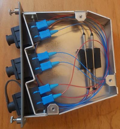
The semi-transparent mirrors are deflecting some of the light of the cable towards the capture device, while letting the rest pass on to the other side of the production link. For this kind of access no electricity is required at all, as you can see in the following picture of one of my old Splitters I opened. This will make TAP vendors cringe, because it can affect the TAP efficiency (dust, bend cables) if you’re not careful, so don’t try this at home. It’s easy to see that there is no electricity required, and the splitting happens in the two metal tubes, with the incoming blue production cable on one side and the blue production/red monitor cable on the other:
Modern splitters can do this for a range of physical link speeds – meaning you don’t need to buy multiple devices to be able to capture at 1Gbps and 10Gbps but you can do it with one and the same. In fact, the same splitter could technically be used for even higher speeds, but at least for multimode the connector types are different from 1/10Gbpsto 40/100Gbps, requiring a different device.
If you look for optical TAPs/splitters you’ll notice that vendors usually state something called a “Split Ratio“: it’s the amount of light that is deflected by the mirrors for capture. Typical ratios are 70/30 and 50/50, meaning 70% light for the production and 30% for the capture, or 50% production, 50% capture. Now, a word of warning: I’ve seen people go for a 90/10 ratio, out of fear that taking away light from the production link may cause problems – which can happen for long distance links. While this approach will certainly make sure that that doesn’t happen, the remaining 10% of light for capture is sometimes too weak. In which case the capture device won’t be able to establish a link on the capture cards. I myself prefer splitters with 70/30 split ratios, and never had a problem with signal strength on the production link.
Another attribute to consider is the connector type you need for the splitter. There are quite a number of different optical connectors and not always are the connectors used by the network the same type as the ports your capture cards. Most common are LC connectors by now, replacing the older and more bulky SC connectors.
Inserting a splitter the correct way can be a challenge sometimes – when you put it into a link and check that the production cables are up and running again it doesn’t necessarily mean that you’ll get packets on the capture output links. Because it is quite common in my experience that the cables are inserted so that the light passes the mirrors from the back instead of the front, so it will not be mirrored correctly. If that happens, unplug the production link cables and switch RX/TX on both sides to make it work. This also means that you need to plan for a maintenance window of at least 15 minutes to insert the splitter because other than copper (where inserting a TAP can be done under a minute, and often in just a few seconds) you may need the time to check and switch cables. And always remember: never look directly into a fiber optical link to check for light as the lasers can be strong enough to permanently damage your retina!
If you wonder why full duplex splitters only have three ports while copper TAPs have four – the splitter uses just on single physical port to give you access to both output links:
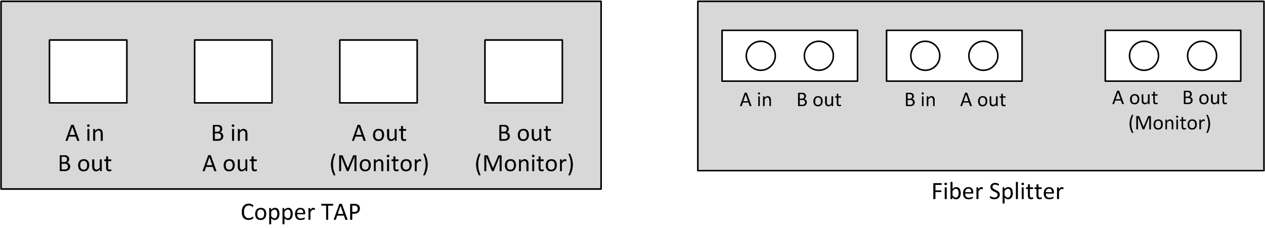
Figure 6: Full duplex TAP and Splitter port schematics
This means that you simply use a normal optical cable for the monitor port of the splitter, but you separate both connectors on the other end and plug them into the receive port of the capture device, while the transmit ports are “blind”.
The Packet out of order problem
For a full duplex TAP the attached capture device needs to have two network ports to receive the packets, and aggregate them into a packet stream during capture. This is more tricky than it sounds, because merging incoming packets in the correct order is not as easy as you may think. Very often people assume that it’s enough to capture simultaneously on any two standard network cards and results will be fine. But more often than not, they won’t be. The problem is that two network cards in one computer aren’t always able to deliver incoming packets to the capture process immediately:
Figure 7: Out of order capture using multiple NICs
As you can see, packets arriving at the upper network card are accepted faster than those of the lower network card – this is something that frequently happens if you use standard PC network cards, because in normal network operations it doesn’t matter if a packet arrives a few micro- or nanoseconds earlier. The network stack will simply sort them out before delivering them to the application. In capture situations, out of order packet arrival at the capture process can be very annoying:
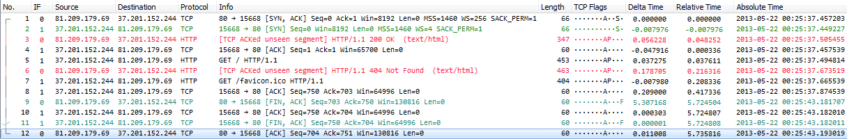
Figure 8: Packets out of order after capture
If you look closely at packet 2 there’s a SYN packet coming in after a SYN-ACK. And in packet 3 you’ll see a “HTTP 200 OK” packet before the handshake is complete, and before the GET request is sent. The delta time between some of the packets is negative, telling you they arrived too late at the capture process. If you wonder how the time stamping works for standard network cards, check this blog post.
There is a fix for this problem, using reordercap.exe, which is part of the Wireshark installation:
[D:\Traces]reordercap "Out of Order Sample.pcapng" "Out of Order Sample Reordered.pcapng"
12 frames, 3 out of order
The resulting trace file looks like this:
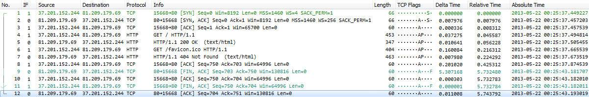
Figure 9: Packets reordered by absolute timestamp using reordercap
If you want to avoid out of order captures using a full duplex TAP, the only reliable way is to use a professional FPGA based multi port capture cards that are able to merge the incoming packets within the card. Basically, that’s what I do when I capture using a full duplex TAP – I have a range of capture devices that can do this, including two old Network General S6040 19″ rack sized distributed sniffers with up to 4 full duplex capture boards. We’re going to look at these special capture cards in another post of this series.
Aggregation TAPs
An aggregation TAP is similar to the full duplex TAP in the way of how it’s inserted into the link:
Figure 10: Inserting an aggregation TAP into a link
The difference to the Full Duplex TAP is that the aggregation TAP has only one “aggregated” output link, so it’s much more similar to what a SPAN port does: it will merge packets sent and received on the link into a single output. This means that a single network card is enough to capture the packets without having to worry about out-of-order arrival, because the TAP will make sure the packet order is correct.
The problem with aggregation TAPs is that they may drop packets if the sum of receive/transmit bandwidth exceeds the output bandwidth – so if you’re using a 1Gbps aggregation TAP with a 1Gbps aggregated output link, the total bandwidth can be as large as 2Gbps, leading to drops on the aggregation TAP again. To avoid that kind of problem you can use an aggregation TAP with an output bandwidth greater than the maximum aggregated production bandwidth. One special solution to this are USB3 aggregation TAPs that inserted into Ethernet links just like normal TAPs, but provide the capture output via USB3 cable (with a total bandwidth of up to 6Gbit/s, which is more than enough for the 2Gbps aggregated maximum of a 1Gbps full duplex link).
Since they are much more complex than full duplex TAPs, link aggregation TAPs are generally more expensive, usually starting at price tags above $1000/1000€. Simple full duplex TAPs (simple meaning: no fancy additional management/LCD display) are often available for a few hundred Dollars/Euros.
Problems with TAPs
TAPs offer the best precision for network captures in general, but there are a few situations where results may not be as good as they should be. This mostly concerns aggregation TAPs of course, when the aggregated bandwidth exceeds the monitor/output link bandwidth. In that case you’ll have to live with dropped packets sooner or later. Some aggregation TAPs have a buffer to help when peaks hit the links, but if the bandwidth is maxed out the buffer will only help for so long, and drops are coming next.
The second common problem is that you have a perfect full duplex TAP setup, but your capture device can’t record all of the incoming packets correctly. While this is not a TAP problem in itself, it should be something you consider when going for a TAP capture.
Low cost TAPs
I bet there are some people who shook their heads in disagreement when they read the price ranges stated in the paragraph above, because they don’t think that TAPs have to be that expensive. Well, that’s true, but it depends on what you want to do. There are very cheap full duplex TAPs that you can buy or build for a handful of Dollars, or aggregation TAPs that are less than 200 Dollars or Euros. Reasons for the price being so significantly low is that they are always limited to copper, often to 100MBit or less, and lack the precision and feature set of the more expensive brands. In my experience they usually
- do not come with a fallback mechanism on power failure, limiting them to capturing user traffic only (certainly not data center stuff)
- allow injecting packets into the production network
Since inserting a copper network TAP into a production link adds another device that can fail you should make sure that your TAP supports fallback on power loss. Having two redundant power supplies is a good idea, though it’s not as critical as you might think if the fallback on power loss exists.
By the way, in case you’re wondering why there are only “do-it-yourself” copper TAPs for 100Mbit or less, and no similar Gigabit TAPs: that’s because copper Gigabit links are piggybacking the signals of sender and receiver on four wire pairs of 250MBit each. So a device in the middle has no chance to know which side put a bit on the wire, because only sender and receiver can subtract their own signal from the incoming signal and determine what the other sent. Which is why Gigabit copper TAPs:
- are much more complex to build than 100MBit copper TAPs
- need to sync their own ports to the both links they’re connected to, effectively meaning a layer 1 Man-in-the-Middle approach (no true passive listening possible)
- are not capable of capturing link auto negotiation information, unlike full duplex fiber TAPs – because copper TAPs need to negotiate their own links before they can get access to anything.
TAP references
I personally use/used the following TAP myself (with NetOptics now being a part of Ixia):
- NetOptics Teeny TAP 10/100 copper full duplex (tiny, dual power supply, not used anymore)
- NetOptics TP-CU3 10/100/1000 copper full duplex (noisy, dual power supply, used sometimes in data centers)
- NetOptics 96443 10/100 copper aggregation TAP (noisy, dual power supply, not used anymore)
- NetOptics 96042G-30 fiber full duplex 1Gbps splitter (70/30 split ratio, no power required, only used for old SC connector type links)
- DATACOM FIBERtap F50/50/50-M 1005 fiber full duplex 1Gbps splitter (50/50 split ratio, no power required, only used for old SC connector type links)
- Garland Technology OM3702 dual 1/10Gbps splitter (70/30 split ratio, no power required, LC connectors, dual TAP for tapping two links simultaneously)
- Garland Technology P1GCCA 100/1000 full duplex / aggregation / SPAN copper TAP (configurable mode via DIP switch, quiet, good for laptop and FPGA captures)
- ProfiTAP 10/100/1000 ProfiShark 1G link aggregation copper TAP (USB3 output, good for Laptop captures, quiet, software configurable)
I and other members of my team had very bad experiences with NetOptics (iTAP 1GBit copper, with an LCD display) and older DATACOM link aggregation TAPs, so I generally do not use them in capture situations anymore. My rule is that the fewer bells and whistles a TAP has, the better it is. These days, I prefer the Garland Technology and the ProfiTAP devices, because they are portable, configurable, quiet and reliable. Which one of these I use depends on the capture scenario.
Update 08 Feb 2017: just found out that the Garland P1GCCA doesn’t support 10MBit/s, which means that there will be no link if at least one connected device sets link speed to 10 MBit/s. The newer Garland P1GCCAS seems to be triple speed, supporting 10/100/1000, but I don’t have one, so I can’t check.
Update 02 Apr 2018: Added the Garland OM3702 fiber tap, as I was fed up with having to use fiber adapter cables for my old SC connector splitters.
Buying TAPs/Splitters
If you’re going to buy an optical TAP / splitter, check these parameters to match your requirements:
- Connector type of the production link (usually LC now)
- Connector and link type of the monitor link (you can buy TAPs/splitters that have fiber for production and copper for monitor ports and vice versa)
- fiber core – there’s usually single mode and multi mode fibers. Make sure you get the right one, and check for the diameter, too (I have a few taps with 50/125 micron diameters while most are 62.5/125 micron. Most modern TAPs are now 50 micron I think, but that’s something your TAP vendor can tell you).
- split ratio – I usually go for 70/30, but I also have some that are 50/50.
- in case of doubt, talk to your TAP/splitter distributor. In my experience they know their products well and will be happy to help you find the right one.
Deploying TAP/Splitters
Here are some general personal opinions and tips regarding network TAPs and splitters:
- always test new TAPs before deploying them. Tests should include at least
- test captures for the copper/fiber speed you expect to work with
- TAP power failure behavior
- TAP power restore behavior (it’s good to know how long a TAP takes to reestablish links to prevent personal panic moments when it doesn’t instantly – I’ve seen some taking up to 10 seconds)
- TAP packet injection behavior
- for splitters, check and swap fiber cabling if link is up for production but you capture nothing or only one-sided communication. Putting a splitter in and letting the rest of the maintenance window pass (because “the production link is working, so everything’s fine, right?”) before checking the capture works too is a common mistake, and can cost you dearly.
- again, the less features a TAP has, the better – those with fancy management / packet statistics / LCD display features tend to break/fail much more often than simple full duplex TAPs.
- It’s next to impossible to argue against fiber full duplex TAP capture results (unless the capture system wasn’t fast enough and dropped packets). It’s the truth of what happened on the network, plain and simple, with the highest precision you can possibly get.
- Cheap TAPs or “TAPs” (calling something a “TAP” doesn’t necessarily mean it’s what you expect it to be) almost always come with some unexpected surprises, so make sure to test them thoroughly before you risk using them in a critical link. They’re usually fine for low bandwidth user workstation captures where you don’t care about high precision and network robustness.
- Using a full duplex TAP in combination with a professional FPGA based capture device is my preferred option, but not always possible
- Make sure you use TAPs that do not allow packet injection on the capture output. It makes it much easier to deal with the typical customer situation of someone from their staff approaching you with “hey, you’re capturing, right? You’re disturbing the network. We have big problems because of you!”.
- In situations where you’re putting a TAP into a PoE link you should make sure that your TAP can deal with that. I only realized that I was inserting a NetOptics TeenyTap into a 100Mbit VoIP phone PoE link for the first time without knowing it would work in the second I did it – boy, was I relieved when it didn’t go up in flames 🙂
Final Words
In this post I only covered basic TAPs – there are much more TAPs models out there, and I’ll get back to them in another post at some point.
Performing a capture using TAPs is the most precise way of getting access to network packets, and among TAPs you can’t get more precise than with a full duplex passive fiber optic splitter, because it basically gives you some of the original “light” from the production link without any delay, modification or aggregation. Here are some typical scenarios where you should deploy TAP(s) to get results that are precise enough (if this list seems familiar – it’s the same as in the SPAN port post, but the other way around, of course):
- searching for a device responsible for lost packets
- determining exact timings, especially with total end-to-end delay less than 50 milliseconds
- proving packet existence on the link a device is attached to
- overall network load too high to be handled by the monitor port
- forensics investigations where you can’t afford any kind of packet drops (leading to not being able to reconstruct binary payloads)
As soon as you decide to go TAP (which is required in some situations, as I pointed out in the SPAN port part of this series) you need to think about your capture device. If you want to use an aggregation TAP you need to make sure the total bandwidth doesn’t exceed the output bandwidth of your TAP. If you use a full duplex TAP you need a capture device with two network cards/ports, and think about out of order arrival of packets. For me, going full duplex TAP always means using a professional FPGA based capture card as well.
If you’re interested in how fiber optic cables work: there is a nice guide available that explains it with a lot of animations.
Other parts of this series
Part 1: Ethernet Basics
Part 2: Speed, Duplex and Drops
Part 3: Network Cards
Part 4: SPAN Port In-Depth
Part 6: Planning Network Captures
“The power loss reaction time of most TAPs is less than a second, which is fast enough to keep most connections alive easily.”
What? No.
A windows machine will destroy all of its TCP sockets on link loss.
Most DHCP clients will discard their lease (Cisco routers are a curious exception)
Bridges running STP will go into listening/learning mode when a link bounces (even with portfast we’re looking at a couple of seconds)
L3 interfaces on routers will discard everything learned from routing neighbors.
There’s almost no place that’s interesting to tap which won’t have an extended outage when one of those “safe” copper taps goes “click.”
I tested it just now with a Cisco router and my Macbook, both plugged into a Cisco switch. Each transition of the tap relays (power up or down) caused a link loss event on the switch, the macbook and the router.
Anyway, what did you use to make those animations? They’re beautiful.
Interesting – I agree that end nodes are often confused by link loss and do the things you mention, but I’ve also see Windows PCs and laptops survive a short link down without DHCP renegotiation. STP is probably the bigger problem, as I’m usually only concerned with link down situations for infrastructure links. Servers should run with static IPs so they may have less trouble with link loss compared to dynamic IP devices. But they may still close application sockets, which sucks.
But in the end you don’t want to see a power failure, so redundant power supplies are a good choice for all links where a link loss are more than just a little inconvenient. So I updated the post accordingly, and thanks!
I use Visio to create the computers and network devices, then import them into Powerpoint and add animations in there. Afterwards, I capture the animation using Camtasia and produce as GIF. By using PowerPoint I can also re-use the animations in presentations and workshops 🙂
It seems that “link lock” and similar feature descriptions from vendors of 1000BASE-T taps drive me crazy. I find the marketing materials borderline dishonest.
Thanks for the info on your drawings. I may try copying your procedure.
I’ve just had a look at the ProfiTap product line. Wow! Hardware timestamping with GPS and PPS inputs? Fantastic.
Do you have one of these handy? I’m curious to know the USB vendor/product codes it reports.
When using the timestamp feature, is it possible to have the timestamps appear *only* in the usual pcap/pcapng timestamp fields, without adding extra data to the frames in the capture file (like, say the VSS scheme does)? I’ve got some not-in-wireshark dissectors that wouldn’t like extra garbage in the frame, but which *will* benefit from better timestamps, even if they’re limited to the microsecond precision available from libpcap.
Also, you may be amused to note that I’ve written an article somewhat similar to this one: http://www.fragmentationneeded.net/2012/01/ethernet-taps-dont-get-me-started.html
Sorry for the delay – your post ended up in the SPAM queue for some reason. I have a ProfiShark 1G and will check USB vendor/product codes as soon as possible for you. As far as I remember the high resolution timestamp is added as extra bytes trailing the frame, but I can check that in some tests, too.
Thanks for the link, your blog looks quite interesting and I haven’t seen it before.
Thanks for another great post Jasper, although I will not be going to the level of taps myself (in my current role), it is good to have an understanding of the process and types of taps available (good background knowledge)
Thanks
Ernest
One more time a great post! I really enjoyed it.
Thanks, Jasper!!
Johannes
Wonderful series of posts. Thank you.
Will you have a post that focuses on the capture device(s) themselves? Will a standard laptop suffice, or is it important to use something specific there as well?
Thanks Mike, and yes, capture devices will be focused on later in the series as well. A standard laptop is good enough up to 300 or 400 Mbit/s in most situations, but depending on the capture situation it may not be good enough (e.g. when you need to TAP a 1GBit/s Link full duplex, you need a device with 2 network ports to receive the data).
Hi, I have in my office intermittent network problems. I read your article about intermittent, what tap do you recomended for start, one for 100 Mbit/s ?
If you want to go full duplex, I’d probably choose the Garland PT100 or the ProfiShark 100M. The Garland is better if you have a capture device that requires two Ethernet links, and the ProfiShark is good choice if you plan to use a Laptop equipped with USB3 ports to capture the packets.
The information in these posts are very valuable Jasper.
Thankyou for putting so much effort into creating them.
The animations are very good and I can imagine that you’ve spent hours tweaking them to get them exactly right.
You’re a good bloke. (Highest possible Australian compliment!)
Thanks, Philip, you’re welcome 🙂
Hi Jasper,
thanks for that great article.
One thing that is not covered though, how can I configure the SFP or SFP+ interfaces on a linux/windows server to come up and capture traffic when an optical TAP output is connected only to RX port; while the TX port has nothing in it?
Hi Mustaffa, thanks! I have to admit that I only captured optical links coming from TAPs with professional capture cards which don’t expect to use TX anyway. I never used COTS hardware for that so far, so I hadn’t experienced this problem. But it’s a very interesting question and I’m going to check it out as soon as I can!
Hej Jasper, is there an follow-up on this question?
Have you tried it in the meantime?
Again, thanks a lot for this blog 🙂
Hi Jasper,
regarding fiber TAPs you mentioned that the “Monitor Port” outputs RX and TX side (A out B out). This is a LC cable in Monitor-Port in our case, connected to a capture appliance with SFP inserted. Now, the problem is that we of course only see unidrectional traffic, because this SFP hat RX/TX side and not 2x RX. How do I get both sides?
Do I need to spilt and connect this one LC patchcable to 2 different SFPs on their RX side instead of one? Or 2x LC cable with only one cable core (which is the same but would make it easier)
Thank you!
Hi Guido,
yes, that’s what you need to do – split the cable and put the separate connectors into the RX side of both of the capture card ports. Or run single cable core cables, but I usually do the splitting because it is easier for me, and I can recombine it later if I remove the casing carefully enough (not breaking it)
Cheers,
Jasper
Important hint for fiber splitters: Connect monitor ports to capture device BEFORE you connect the two components. Otherwise the links did not come up. Seems there is a TX power adjustment for SFPs and TX power is higher when monitor port is connected.
That’s a good tip, thanks!
Thanks a lot for this series. It helps a lot!
There ist still one question, that I’d liek to ask:
Is there any capture-card that you know of, that produces an output of the merged streams (from passive fibre tap) and can be seen as a (virtual?) network device inside the system so that the data could be used for live monitoring and DDos-detection like FastNetMon?
Thanks in advance!
Hi Ben, thanks, good to know it helped.
So if I understand your question correctly you are looking for a capture card that merges the two output streams from a full duplex tap into one single stream? As far as I know all FPGA based professional capture cards can do this, e.g. Endace, Napatech, Accolade, Fiberblaze and possibly others. I have worked with Endace and Napatech cards and they work fine. The only downside (at least for Napatech) is that if you configure the cards to merge two ports into a single stream it will lose the information which port the packet was seen on – but that is usually not required for troubleshooting anyway.
Thanks for your answer.
Yes, you understood my question, but not entirely.
The point is, that FastNetMon is only capable to grab data directly of an network-interface by itself or to work of flow-information (this is what I understood writing with their support).
So that’s why I was aksing, if any of these capture-card provides a virtual network interface that you could bind the software to.
Unfortunately FastNetMon neither supports libpcap or PF_RING so that nearly all if not all of the cards you named could be used with it.
As I wanted to find a solution that can be used for a fast live DDoS-detection as well as monitoring a whole bunch of other network metrics per DPI and store them in a time-series-database I therefore can not use FastNetMon (unfortunately).
But I’ve found another DDoS-detection-software that ist capable of working with a capture-card so the problem is solved.
Thanks a lot!