Capturing packets of VMware machines, part 2
In the first post I described how to capture packets in VMware vSphere environments when dealing with standard vSwitches. While that works fine, some larger installations have an even better way of doing network captures of virtual machine traffic, provided by the so-called Distributed vSwitches. Unfortunately, those special vSwitches require a Enterprise Plus license, so all installations that run on Enterprise or less do not get these and have to stick with standard vSwitches.
The main reason to use Distributed vSwitches is that you can create single logical vSwitch instances that span across multiple ESXi nodes instead of having to create identical vSwitches on each hypervisor. Also, VMware seems to always put the cool new stuff into the distributed vSwitches, so there are quite a few reason to use them if you can: they provide e.g. NetFlow options, active LACP capabilities, private VLANs and – what helps with troubleshooting a lot: Port Mirroring.
So let’s take a look at an sample setup of a Distributed vSwitch running in a vSphere 5.0 environment, which isn’t the latest version – but I’ll get to a newer setup in a post in the future, because it gets much more complicated. This test dvSwitch is only used by one hypervisor, but that is enough for a capture test setup. 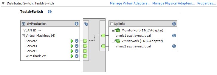
Let’s assume that we want to capture the traffic of Server1. To do that we have to create a monitor session on the Distributed vSwitch by moving to the “Networking” view of the inventory.
Important: do not enable promiscuous mode on the portgroup you are using the monitor session on or you’ll end up with duplicate frames. Either use promiscous mode or a monitor session, but not both at the same time!
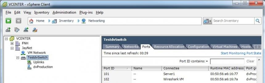
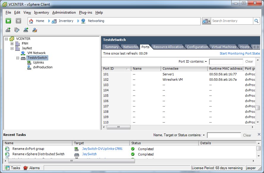
The first thing we need to do is to write down the ports the VM we want to capture traffic of and the port of the capture VM are connected to. In this case the Server1 VM is at port 101, and the capture VM at port 102, as you can see in the next screen shot:
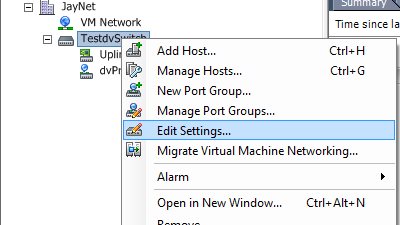
Now, edit the settings of the Distributed vSwitch. Make sure that you do not right click on a port group or any other object in the inventory tree or you’ll not get to the right settings dialog:
Don’t get distracted by all the tabs that offer other interesting settings and select the “Port Mirroring” tab:
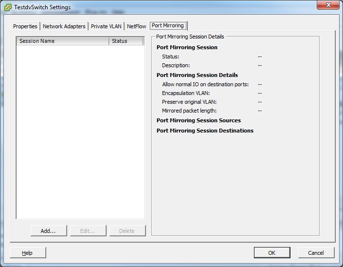
As you can see there is no port mirroring configured at the moment, since all details fields are empty. Click on the “Add…” button to create a new monitor session. A dialog will open where you can enter a name and a description. It is usually good practice to use descriptive names as well as putting in a good description, because you may need to decide later if that session is still necessary or good for removal. A name like “Span Session 1” will most certainly lead to it being removed by the next administrator that wonders what it is good for (well, mine is temporary anyway, so it doesn’t matter):
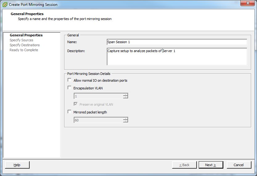
The interesting things are the checkboxes in the “Port Mirroring Session Details” pane. Here’s what they do:
- Allow normal IO on destination ports: the traffic you’re going to monitor has to be copied from the source port to a destination port. At that destination port the capture VM will record any frame that is copied. By default, that destination port will not allow the capture VM to send any data back into the switch, which makes perfect sense – you don’t want your recording device to inject traffic into the link. It should only listen and record data.Sometimes, you want to be able to send data on the capture link, e.g. for allowing the vSphere client to configure the settings. I usually recommend adding a second management network card to do that and keep the capture card as “receive only” card. Anyway, if you know what you’re doing you can enable normal I/O operations with this checkbox.
- Encapsulation VLAN: if checked, you can encapsulate the frames on the monitor port into a VLAN of your choice. The sniffer running on the monitor port will see Ethernet frames with VLAN tags, and if the original frame was already tagged you can choose to keep it as well. In that case you’ll end up with double VLAN tagged frames.
I have say that I tried this feature on the vSphere 5.0 setup and it didn’t work. At all. There was no VLAN tag added to the copied frames, no matter what I tried. I’ll have to recheck this behavior with a 5.1 setup again. I even tried a couple of different capture cards (virtual as well as physical) because some cards discard VLAN layers, but I used at least 2 that are proven to handle VLAN tags correctly, so it’s not the capture equipment that has a problem.
- Mirrored packet length: this setting allows you to cut copied frames at a specified offset, e.g. if you set this to 60, all frames that are copied will be 60 bytes long with anything else discarded at the dvSwitch level. This may seem familiar with the Wireshark capture options setting (“Limit each packet to… bytes“) where you can do the same, but it isn’t: other than the Wireshark setting you will record a frame that is 60 bytes long and lose the information about how long it really was! The Wireshark setting will record 60 bytes and store the information about the real length in the packet headers instead. While that may sound like a minor advantage it is a lot more than that, because when Wireshark doesn’t know that the original frame was longer than what it sees it will annoy you with tons of checksum error messages, TCP lost segment warnings etc. that can throw you off. Rule of thumb: don’t limit the packet length on the mirror session! Do it in the capture software if you have to.
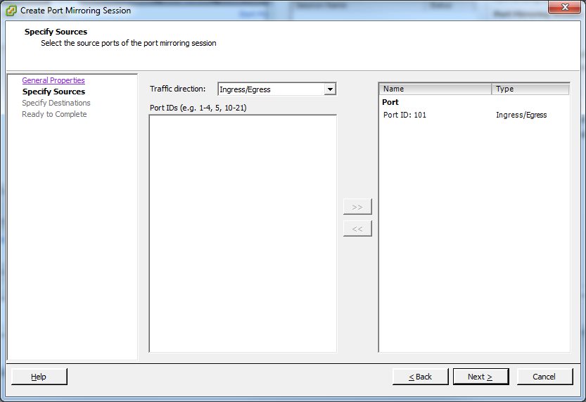
Next step is to add a source port. There are a couple of things you need to do here:
- find out the port ID number where the VM you want to capture traffic of is connected to. You need to do that at the port group level looking at the “Port” tab as we did at the start.
- There is no list of ports you can select from. You have to enter them as text in the “Port IDs (e.g. 1-4, 5, 10-21)” box in the middle of the dialog and press the “>>” button to add them to the list on the right.
- Usually, selecting the “Traffic direction” of Ingress and Egress is correct, but sometimes you may only want one of them.
Now we got the source covered, so the next step is the destination port. There are two possibilities here: you can either mirror the traffic to another VM, or (and that is pretty cool) you can mirror the traffic to an uplink port. That means that you need a free physical network card in your ESXi where you can connect a physical capture device to record the traffic of a VM, so it is sort of an outbreak for virtual packets. In our case, we’ll do a virtual capture, so we add the port of the capture VM:
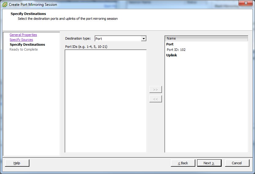
The last step is to verify the setup and enable the monitor session by activating the check mark before pressing the “Finish” button:
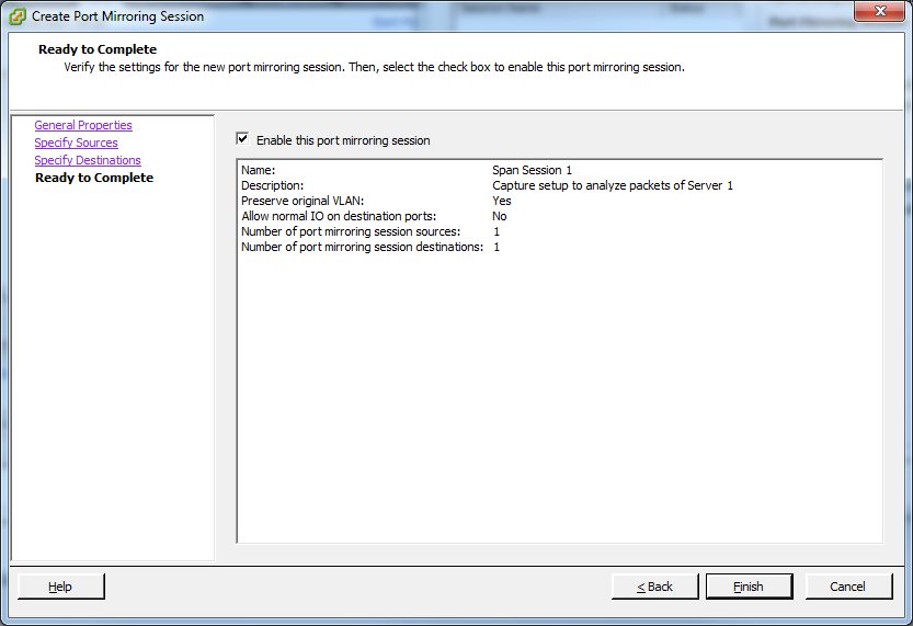
Now, when you start the capture software (usually Wireshark, but some use NetMon or tcpdump etc.) in the capture VM, and you should see everything that the monitored VM does on the network.
Summary: distributed vSwitches are very helpful when you need to capture traffic of a VM since you can do it without having to do the duplicate port group trick I described in the first post. Also, you can “exfiltrate” traffic via a physical NIC and record the data on a physical capture device, which takes away the problem of the I/O generated on the hypervisor/storage by writing packets to disk.
Great posts Jasper, nice trick with the separate portgroup and good to know the possibilities of the dvSwitch!
Thanks. There will be more to come on this topic, since I have encountered some strange things with the dvSwitch I use right now and I’m going to investigate when I have the time (and post about it).
That’s a wise answer to a tricky qutsoien
Do you know this method or evn tried?
http://kb.vmware.com/selfservice/search.do?cmd=displayKC&docType=kc&docTypeID=DT_KB_1_1&externalId=1031186
and yes i know that only for 5.5…
Or this:
http://kb.vmware.com/selfservice/microsites/search.do?language=en_US&cmd=displayKC&externalId=2051814
yes, I know both of these methods and have tried them, but I didn’t have time yet to document them well enough to make a good blog post out of it. I plan to do that though as soon as I have a little time for some lab time.
Jasper, Great articles. In the Prt 1 discussion you mention the need to monitor the I/O of packets being copied to the VMDK, as this will have a performance impact on the storage infrastructure. What kind of packet capture rates have you seen when capturing in a virtual instances (I understand this will vary widely depending on infrastructure and setup)? Also, wouldn’t the packets be kept in RAM memory (which is also where the virtual switch is maintained) and not transferred to disk if the capture buffer is based on RAM memory and not disk?
I have run captures on virtual instances up to 50-100 MBit per second, but you need to be careful even with that rate depending on your storage. I had big trouble once when I captured to a VMDK on a iSCSI storage system that was only connected with 2x 1GBit links, resulting in huge I/O bottlenecks for the VMs running on the same storage. My current setup is to capture to dedicated storage to avoid those problems, meaning that I have a second SAN that is my capture target (which I use as storage for VM backups otherwise, which isn’t time critical as live VMs are).
Usually, packets are not kept in RAM for long, e.g. Wireshark only uses 1 or 2 Megabytes of RAM by default – this means that packets are almost instantly written to disk. If you create a RAM disk in a VM you can capture to that and avoid disk I/O, but you need to make sure you’re not over-committing your memory (and maybe do a 100% RAM reserve for the capture VM, just to make sure).
Jasper, these are great articles, however, I have another question. We are using dVswitches throughout our infrastructure, but we have problems capturing packets when the Wireshark VM moves hosts. If it is on the same host as the system we want to monitor everything works fine but once it migrates to another host we do not capture anything. Any suggestions about how to fix this?
Thanks again for the great articles!
Yes, that is a problem. dvSwitch captures only work if both monitored and monitoring VM are on the same ESXi host. Unfortunately there is not much that can be done except keeping the VMs together, because the dvSwitches do not have the ability to transport monitored traffic over to another ESXi for capture there (which could be a LOT of traffic in some cases).
What I do is to use DRS rules to keep the capture VM together with the monitored VM, or set both of them to partially automated or manual to keep them from moving during the capture after having moved them manually to the same ESXi.
Hello Jasper,
A question regarding this configuration for dvSwitches: Should I expect to see ONLY traffic for the ports selected, or for all traffic on the dvSwitch? I think that with specific ports (not a source VLAN) then I should see traffic that only would appear on those specific ports.
My config: Using vSphere 5.5, ESXi hosts are 5.5, dvSwitches, all three hosts are on the same ESXi host, test1 is the capture host with two interfaces, eth1 is the capture interface and eth2 is the management interface, test2 and test3 only have eth1, attempting to capture between test2 and test3.
dVswitch is configured as:
promiscuous mode
distributed port mirroring,
Allow normal IO: No
Encapsulation VLAN: —
Preserve original VLAN: Yes
Mirrored Packet Length: —
Session Sources:
Port 30711, Ingress/Egress
Port 30826: Ingress/Egress
Port Mirror Destination:
Port 30830
I don’t have access to the dvSwitch, having to work through another group, unfortunately.
You should only see the traffic from the selected ports when using the SPAN/mirror feature of the dvSwitch. I don’t see why you would also configure promiscuous mode – this is not required for mirroring. Instead, it would explain why you see more packets than you actually want to see. Basically, you mixed two techniques here, giving you results you don’t want. So my advice would be to turn of promiscuous mode and only use the mirroring feature.
That is what I was thinking, or that somehow it was set for VLAN instead of ports.
Without promiscous mode, I was only seeing outbound traffic from each of test2 or test3, and not traffic between the two; that is, from test2 to test44 but not the return, and from test3 to test44 but not the return, and none of the traffic from test2 to test3 or test3 to test2.
Further thoughts?
Thanks,
Jason
Verify that all ports are set to rx/tx mirroring, and make sure all VMs are on the same ESXi. Port mirroring does not work between ESXi hosts. Also, on the capture VM, turn off any firewall or other security software which may block packets.
Promiscous mode turned off, ingress/egress enabled, the two source ports and the destination port are on the same ESXi host, no firewall, etc. on the capture host.
The way this is behaving, with promiscuous mode off, is that traffic from test2 or test3 to most destinations is seen, but not the return traffic from any destination. Traffic for some destinations (seems to be destinations on the same ESXi hosts) is never seen. Traffic from test2 to test 3 is never seen, nor the other direction.
This behavior of only seeing the source traffic would be expected if the port mirroring was configured for egress from the switch into a trunk.
Both test2 and test3 see all the traffic on their local interfaces, as expected.
Strange. Are the dvSwitches v5.5, too? Or are they still an older version? I know that port mirroring prior to 5.5 didn’t work well in some situations. Other than that, I’m running out of ideas – there seems to be nothing wrong with your setup.
Hi Jasper,
Yes, the dvSwitches are v5.5.
I’ve proven with captures that the traffic that the port mirror sends to the mirror destination is only traffic destined for VMs that are on different ESXi hosts. Traffic destined for VMs that are on the same ESXi host as the port mirror destination port is not forwarded to the destinaiton port. The destination port does receive broad/mutli/any-cast. For example, test2 and test3 are on the same ESXi host, test44 is not, test2 or test3 to test 44 is seen, but not test44 to test2 or test3; test2 test3 is never seen.
This behavior seems exactly opposite of what everything I’ve read says, that port mirroring (‘distributed port mirror’) will only work on the same ESXi host.
Extremely bizzare.
I’ll post an update with a solution when (if !?) we get a solution.
Thanks! Jason
Okay, I’ll try to replicate that with my installation to check if I can get the same results.
Hi
I am doing vds port mirroring in same blade between 2 vm
I have promiscuous mode enable, forged packet enable, 1 Uplink
Mirror is on uplink and downlink
My problem is that the mirrored packet are duplicated.
I see each packet twice or more time in the destination port mirror.
That’s probably because of the promiscuous mode. It’s not required for port mirroring. Instead it turns the port group/vds into a logical hub, meaning that all machines on the portgroup/vswitch get all packets. Plus the mirror target port gets another copy, so you’ve got duplicates. Turn off promiscuous mode and you should be fine.